Prepare for Cisco 300-115 exam with best Cisco CCDP 300-115 dumps pdf training resources and study guides download free try from lead4pass. “Implementing Cisco IP Switched Networks” is the name of Cisco CCDP https://www.leads4pass.com/300-115.html exam dumps which covers all the knowledge points of the real Cisco exam. It is the best choice for you to pass Cisco 300-115 exam.
Download Cisco 300-115 dumps pdf training material from lead4pass 300-115 SWITCH – Cisco and pass the Cisco 300-115 exam in the first attempt. High Quality Cisco CCDP 300-115 dumps exam questions and answers (q1-q20) free shared Cisco 300-115 dumps vce youtube demo. The best useful Cisco CCDP 300-115 dumps vce software online download free try.

Best Cisco 300-115 dumps pdf from google drive: https://drive.google.com/open?id=0B_7qiYkH83VROUdnZWRYLTJta1E
Best Cisco 300-135 dumps pdf from google drive: https://drive.google.com/open?id=0B_7qiYkH83VRS21DRS14UlZHNjg
2018 Latest Cisco CCDP 300-115 Dumps Exam Questions And Answers (Q21-Q30)
QUESTION 21
Drag and Drop
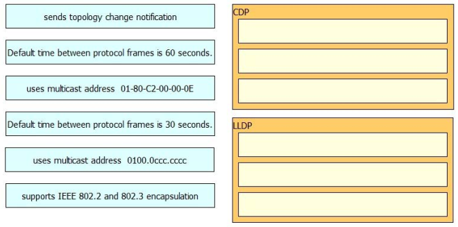
Drag and drop the characteristic from the left to the matching Layer 2 protocol on the right.
Select and Place:
Correct Answer:

QUESTION 22
Lab Simulation – AAA dot1x
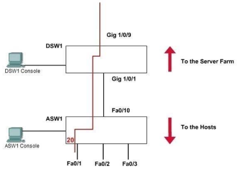
SWITCH.com is an IT company that has an existing enterprise network comprised of two layer 2 only switches; DSW1 and ASW1. The topology diagram indicates their layer 2 mapping. VLAN 20 is a new VLAN that will be used to provide the shipping personnel access to the server. Corporate polices do not allow layer 3 functionality to be enabled on the switches.
For security reasons, it is necessary to restrict access to VLAN 20 in the following manner:
– Users connecting to VLAN 20 via portfO/1 on ASW1 must be authenticated before they are given access to the network.
Authentication is to be done via a Radius server:
– Radius server host: 172.120.40.46
– Radius key: rad123
– Authentication should be implemented as close to the host as possible.
– Devices on VLAN 20 are restricted to the subnet of 172.120.40.0/24.
– Packets from devices in the subnet of 172.120.40.0/24 should be allowed on VLAN 20.
– Packets from devices in any other address range should be dropped on VLAN 20.
– Filtering should be implemented as close to the serverfarm as possible
The Radius server and application servers will be installed at a future date. You have been tasked with implementing the above access control as a pre-condition to installing the servers. You must use the available IOS switch features.
A. See the explanation
Correct Answer: A
Explanation:
1. Verification of Pre-configuration:
a. Check that the denoted vlan [vlan20] is created in both switches and ports [fa0/1 of ASW1] are assigned.
b. Take down the radius-server ip [172.120.39.46] and the key [rad123].
c. Take down the IP range [172.120.40.0/24] to be allowed the given vlan [vlan20]
2. Configure the Port based authentication on ASW1:
Enable AAA on the switch:
ASW1> enable
ASW1# conf t
ASW1(config)# aaa new-model
The new-model keyword refers to the use of method lists, by which authentication methods and sources
can be grouped or organized. Define the server along with its secret shared password:
ASW1(config)# aaa authentication dot1x default group radius
ASW1(config)# radius-server host 172.120.39.46 key rad123
This command causes the RADIUS server defined on the switch to be used for 802.1x authentication.
Enable 802.1x on the switch:
ASW1(config)# dot1x system-auth-control
Configure Fa0/1 to use 802.1x:
ASW1(config)# interface fastEthernet 0/1
ASW1(config-if)# switchport mode access
ASW1(config-if)# dot1x port-control auto
Notice that the word “auto” will force connected PC to authenticate through the 802.1x exchange.
ASW1(config-if)# exit
ASW1# copy running-config startup-config
3. Filter the traffic and create vlan access-map to restrict the traffic only for a range on DSW1 Define an access-list:
DSW1> enable
DSW1# conf t
(syntax: ip access-list {standard | extended} acl-name)
DSW1(config)# ip access-list standard 10
DSW1(config-ext-nacl)# permit 172.120.40.0 0.0.0.255
DSW1(config-ext-nacl)# exit
Define an access-map which uses the access-list above:
(syntax: vlan access-map map_name [0-65535] )
DSW1(config)# vlan access-map MYACCMAP 10
(syntax: match ip address {acl_number | acl_name})
DSW1(config-access-map)# match ip address 10
DSW1(config-access-map)# action forward
DSW1(config-access-map)# exit
DSW1(config)# vlan access-map MYACCMAP 20
(drop other networks)
DSW1(config-access-map)# action drop
DSW1(config-access-map)# exit
Apply a vlan-map into a vlan:
(syntax: vlan filter mapname vlan-list list)
DSW1(config)# vlan filter MYACCMAP vlan-list 20
DSW1# copy running-config startup-config
4. Note:
It is not possible to verify the configuration in this lab. All we have do the correct configurations. Most of the exam takers report that ” copy running-config startup- config” is not working. It does not a matter.
Do not try unwanted/wrong commands in the consoles. They are not real switches.
QUESTION 23
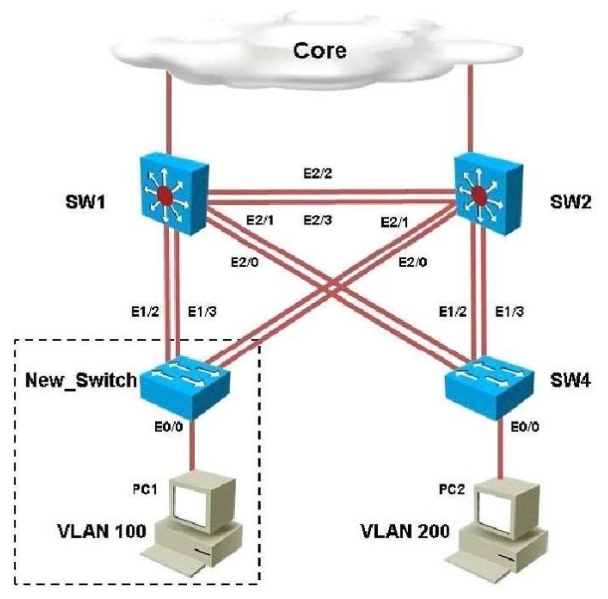
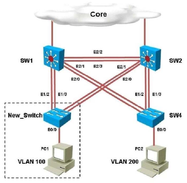
You have been asked to install and configure a new switch in a customer network. Use the console access to the existing and new switches to configure and verify correct device configuration.
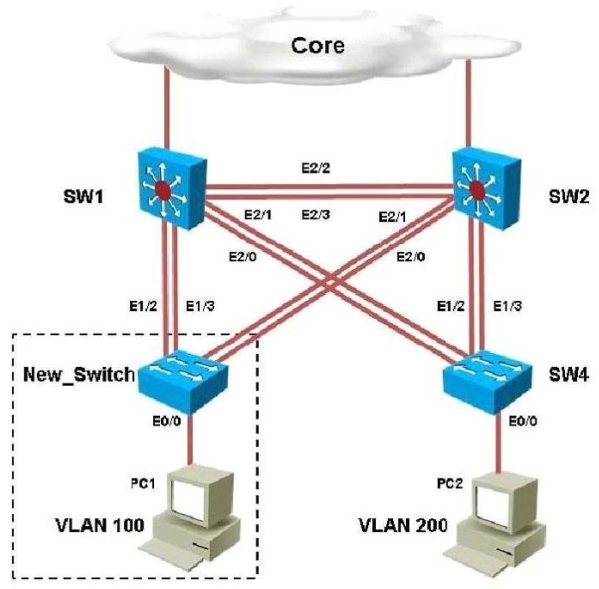
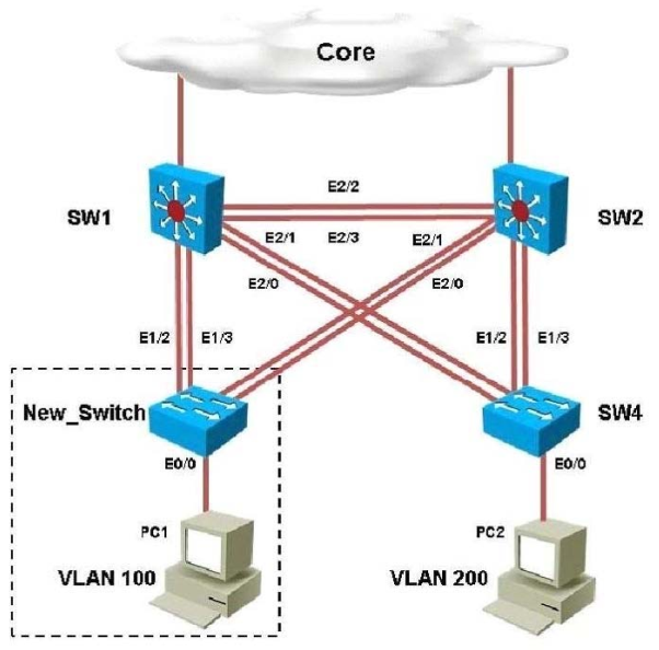
You are connecting the New_Switch to the LAN topology; the switch has been partially configured and you need to complete the rest of configuration to enable PC1 communication with PC2.
Which of the configuration is correct?
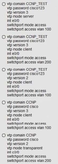
A. Option A
B. Option B
C. Option C
D. Option D
E. Option E
Correct Answer: D
Explanation:
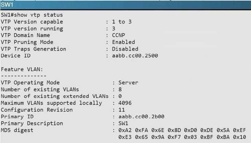
Within any VTP, the VTP domain name must match. So, step one is to find the correct VTP name on the other switches. Logging in to SW1 and using the “show vtp status” command we see this:
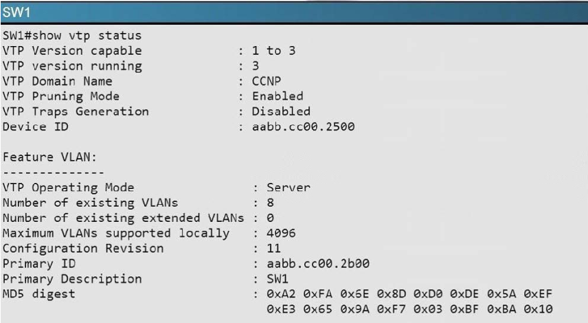
So we know that the VTP domain must be CCNP. This leaves only choice D and E. We also see from the topology diagram that eth 0/0 of the new switch connects to a PC in VLNA 100, so we know that this port must be an access port in VLAN 100, leaving only choice D as correct. 300-115 dumps Note that the VTP versions supported in this network are 1, 2, 3 so either VTP version 2 or 3 can be configured on the new switch.
QUESTION 24
You have been asked to install and configure a new switch in a customer network. Use the console access to the existing and new switches to configure and verify correct device configuration.
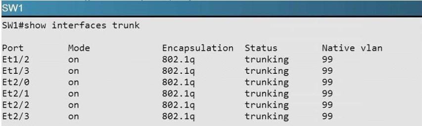
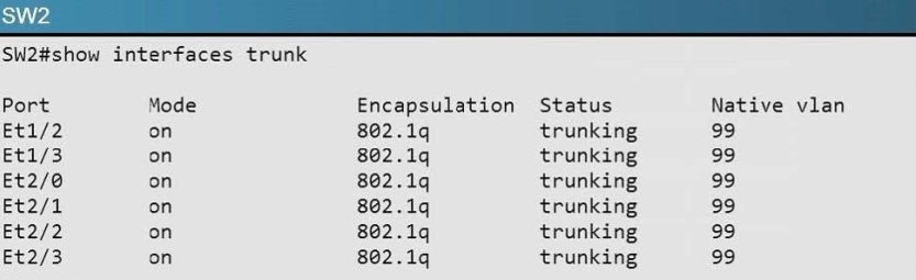
Refer to the configuration. For which configured VLAN are untagged frames sent over trunk between SW1 and SW2?
A. VLAN1
B. VLAN 99
C. VLAN 999
D. VLAN 40
E. VLAN 50
F. VLAN 200
G. VLAN 300
Correct Answer: B
Explanation:
The native VLAN is used for untagged frames sent along a trunk. By issuing the “show interface trunk” command on SW1 and SW2 we see the native VLAN is 99.
QUESTION 25
You have been asked to install and configure a new switch in a customer network. Use the console access to the existing and new switches to configure and verify correct device configuration.
You are adding new VLANs. VLAN500 and VLAN600 to the topology in such way that you need to configure SW1 as primary root for VLAN 500 and secondary for VLAN 600 and SW2 as primary root for
VLAN 600 and secondary for VLAN 500. Which configuration step is valid?
A. Configure VLAN 500 & VLAN 600 on both SW1 & SW2
B. Configure VLAN 500 and VLAN 600 on SW1 only
C. Configure VLAN 500 and VLAN 600 on SW2 only
D. Configure VLAN 500 and VLAN 600 on SW1 ,SW2 and SW4
E. On SW2; configure vtp mode as off and configure VLAN 500 and VLAN 600; configure back to vtp server mode.
Correct Answer: A
Explanation:
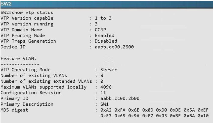
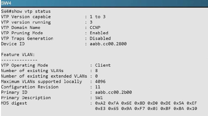
By issuing the “show vtp status command on SW2, SW2, and SW4 we see that both SW1 and SW2 are operating in VTP server mode, but SW4 is a client, so we will need to add both VLANs to SW1 and SW2.
QUESTION 26
You have been asked to install and configure a new switch in a customer network. Use the console access to the existing and new switches to configure and verify correct device configuration.
Examine the VTP configuration. You are required to configure private VLANs for a new server deployment connecting to the SW4 switch. Which of the following configuration steps will allow creating private VLANs?
A. Disable VTP pruning on SW1 only
B. Disable VTP pruning on SW2 only
C. Disable VTP pruning on SW4 only
D. Disable VTP pruning on SW2, SW4 and New_Switch
E. Disable VTP pruning on New_Switch and SW4 only.
Correct Answer: C
Explanation:
To create private VLANs, you will need to only disable pruning on the switch that contains the private VLANs. In this case, only SW4 will connect to servers in a private VLAN.
QUESTION 27
Lab Simulation – MLS and EIGRP
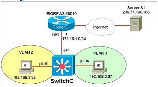
You have been tasked with configuring multilayer SwitchC, which has a partial configuration and has been attached to RouterC as shown in the topology diagram. You need to configure SwitchC so that Hosts H1 and H2 can successfully ping the server S1. Also SwitchC needs to be able to ping server S1. Due to administrative restrictions and requirements you should not add/delete vlans or create trunk links.
Company policies forbid the use of static or default routing. All routes must be learned via EIGRP 65010 routing protocol.
You do not have access to RouteC. RouterC is correctly configured. No trunking has been configured on RouterC. Routed interfaces should use the lowest host on a subnet when possible. The following subnets are available to implement this solution:
– 10.10.10.0/24
– 190.200.250.32/27
– 190.200.250.64/27
Hosts H1 and H2 are configured with the correct IP address and default gateway.
SwitchC uses Cisco as the enable password.
Routing must only be enabled for the specific subnets shown in the diagram.
Note: Due to administrative restrictions and requirements you should not add or delete VLANs, changes VLAN port assignments or create trunks. Company policies forbid the use of static or default routing. All routes must be learned via the EIGRP routing protocol.
A. See the explanation
Correct Answer: A
Explanation:
In real life, there are two ways to configure interVLAN routing in this case:
+ Use RouterC as a “router on a stick” and SwitchC as a pure Layer2 switch. Trunking must be established between RouterC and SwitchC. + Only use SwitchC for interVLAN routing without using RouterC, SwitchC should be configured as a Layer 3 switch (which supports ip routing function as a router). No trunking requires.
The question clearly states “No trunking has been configured on RouterC” so RouterC does not contribute to interVLAN routing of hosts H1 & H2 -> SwitchC must be configured as a Layer 3 switch with SVIs for interVLAN routing.
We should check the default gateways on H1 & H2. Click on H1 and H2 and type the “ipconfig” command to get their default gateways.
C:\>ipconfig
We will get the default gateways as follows:
Host1:
+ Default gateway: 190.200.250.33
Host2:
+ Default gateway: 190.200.250.65
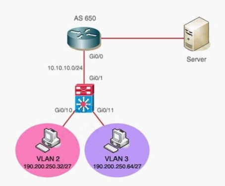
Now we have enough information to configure SwitchC (notice the EIGRP AS in this case is 650)
Note: VLAN2 and VLAN3 were created and gi0/10, gi0/11 interfaces were configured as access ports so we don’t need to configure them in this sim.
SwitchC# configure terminal
SwitchC(config)# int gi0/1
-> without using this command, the simulator does not let you assign IP address on Gi0/1 interface.
SwitchC(config-if)#no switchport
->RouterC has used IP 10.10.10.1 so this is the lowest usable IP address.
SwitchC(config-if)# ip address 10.10.10.2 255.255.255.0
SwitchC(config-if)# no shutdown
SwitchC(config-if)# exit
SwitchC(config)# int vlan 2
SwitchC(config-if)# ip address 190.200.250.33 255.255.255.224
SwitchC(config-if)# no shutdown
SwitchC(config-if)# int vlan 3
SwitchC(config-if)# ip address 190.200.250.65 255.255.255.224
SwitchC(config-if)# no shutdown
SwitchC(config-if)#exit
(Notice: MLS will not work without this command)
SwitchC(config)# ip routing
SwitchC(config)# router eigrp 650
SwitchC(config-router)# network 10.10.10.0 0.0.0.255
SwitchC(config-router)# network 190.200.250.32 0.0.0.31
SwitchC(config-router)# network 190.200.250.64 0.0.0.31
NOTE: THE ROUTER IS CORRECTLY CONFIGURED, so you will not miss within it in the exam , also don’t modify/delete any port just do the above configuration. Also some reports said the “no auto-summary” command can’t be used in the simulator, in fact it is not necessary because the network 190.200.0.0/16 is not used anywhere else in this topology.
In order to complete the lab , you should expect the ping to SERVER to succeed from the MLS , and from the PCs as well.
Also make sure you use the correct EIGRP AS number (in the configuration above it is 650 but it will change when you take the exam) but we are not allowed to access RouterC so the only way to find out the EIGRP AS is to look at the exhibit above. If you use wrong AS number, no neighbor relationship is formed between RouterC and SwitchC.
In fact, we are pretty sure instead of using two commands “network 190.200.250.32 0.0.0.31” and “network 190.200.250.64 0.0.0.31” we can use one simple command “network 190.200.0.0” because it is the nature of distance vector routing protocol like EIGRP: only major networks need to be advertised; even without “no auto-summary” command the network still works correctly. But in the exam the sim is just a flash based simulator so we should use two above commands, just for sure. But after finishing the configuration, we can use “show run” command to verify, only the summarized network 190.200.0.0 is shown.
QUESTION 28
Lab Simulation – MLS and EIGRP
You have been tasked with configuring multilayer SwitchC, which has a partial configuration and has been attached to RouterC as shown in the topology diagram. 300-115 dumps
You need to configure SwitchC so that Hosts H1 and H2 can successfully ping the server S1.
Also SwitchC needs to be able to ping server S1.Due to administrative restrictions and requirements you should not add/delete vlans or createtrunk links. Company policies forbid the use of static or default routing. All routes must be learned via EIGRP 650 routing protocol.
You do not have access to RouteC. RouterC is correctly configured. No trunking has been configured on RouterC. Routed interfaces should use the lowest host on a subnet when possible. The following subnets are available to implement this solution:
– 10.10.10.0/24
– 190.200.250.32/27
– 190.200.250.64/27
Hosts H1 and H2 are configured with the correct IP address and default gateway.
SwitchC uses Cisco as the enable password.
Routing must only be enabled for the specific subnets shown in the diagram.
Note: Due to administrative restrictions and requirements you should not add or delete VLANs, changes VLAN port assignments or create trunks. Company policies forbid the use of static or default routing. All routes must be learned via the EIGRP routing protocol.
A. See the explanation
Correct Answer: A
Explanation:
In real life, there are two ways to configure interVLAN routing in this case:
+ Use RouterC as a “router on a stick” and SwitchC as a pure Layer2 switch. Trunking must be established between RouterC and SwitchC. + Only use SwitchC for interVLAN routing without using RouterC, SwitchC should be configured as a Layer 3 switch (which supports ip routing function as a router). No trunking requires.
The question clearly states “No trunking has been configured on RouterC” so RouterC does not contribute to interVLAN routing of hosts H1 & H2 -> SwitchC must be configured as a Layer 3 switch with SVIs for interVLAN routing.
We should check the default gateways on H1 & H2. Click on H1 and H2 and type the “ipconfig” command to get their default gateways.
C:\>ipconfig
We will get the default gateways as follows:
Host1:
+ Default gateway: 190.200.250.33
Host2:
+ Default gateway: 190.200.250.65
mls>enable
mls# configure terminal
mls(config)# int gi0/1
mls(config-if)#no switchport
mls(config-if)# ip address 10.10.10.2 255.255.255.0
mls(config-if)# no shutdown
mls(config-if)# exit
mls(config)# int vlan 2
mls(config-if)# ip address 190.200.250.33 255.255.255.224
mls(config-if)# no shutdown
mls(config-if)# int vlan 3
mls(config-if)# ip address 190.200.250.65 255.255.255.224
mls(config-if)# no shutdown
mls(config-if)#exit
mls(config)# ip routing
mls(config)# router eigrp 650
mls(config-router)# network 10.10.10.0 0.0.0.255
mls(config-router)# network 190.200.250.32 0.0.0.31
mls(config-router)# network 190.200.250.64 0.0.0.31
mls(config-router)# no auto-summary
mls(config-router)# end
mls# copy run start
QUESTION 29
Lab Simulation – LACP with STP Sim
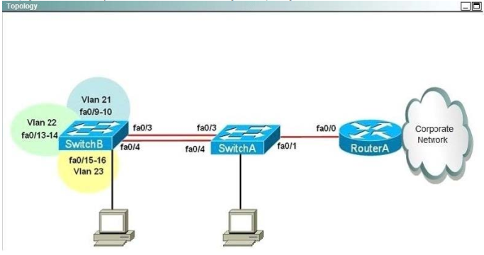
You work for SWITCH.com. They have just added a new switch (SwitchB) to the existing network as shown in the topology diagram.
RouterA is currently configured correctly and is providing the routing function for devices on SwitchA and SwitchB. SwitchA is currently configured correctly, but will need to be modified to support the addition of SwitchB. SwitchB has a minimal configuration. You have been tasked with competing the needed configuring of SwitchA and SwitchB. SwitchA and SwitchB use Cisco as the enable password.
Configuration Requirements for SwitchA
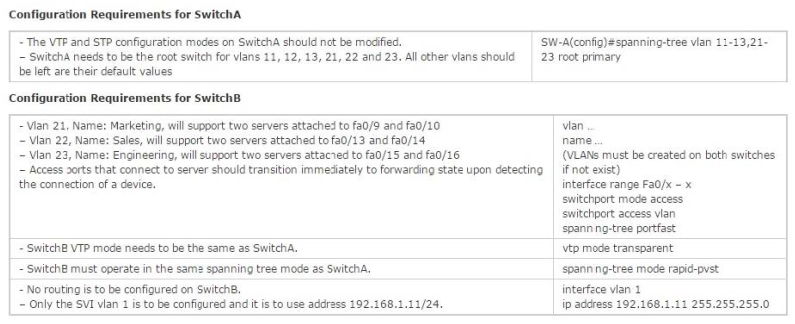
The VTP and STP configuration modes on SwitchA should not be modified.
– SwitchA needs to be the root switch for vlans 11, 12, 13, 21, 22 and 23. All other vlans should be left are their default values.
Configuration Requirements for SwitchB
– Vlan 21
Name: Marketing will support two servers attached to fa0/9 and fa0/10
– Vlan 22
Name: Sales will support two servers attached to fa0/13 and fa0/14
– Vlan 23
Name: Engineering will support two servers attached to fa0/15 and fa0/16
– Access ports that connect to server should transition immediately to forwarding state upon detecting the connection of a device.
– SwitchB VTP mode needs to be the same as SwitchA.
– SwitchB must operate in the same spanning tree mode as SwitchA
– No routing is to be configured on SwitchB
– Only the SVI vlan 1 is to be configured and it is to use address 192.168.1.11/24
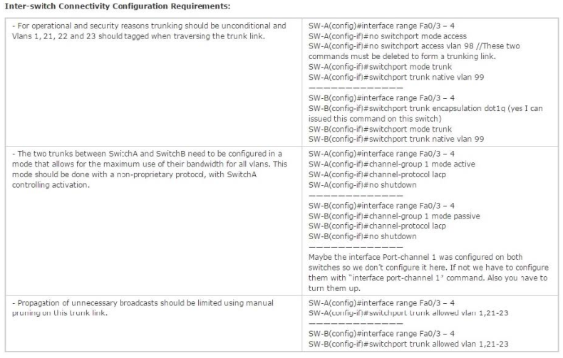
Inter-switch Connectivity Configuration Requirements
– For operational and security reasons trunking should be unconditional and Vlans 1, 21, 22 and 23 should tagged when traversing the trunk link.
– The two trunks between SwitchA and SwitchB need to be configured in a mode that allows for the maximum use of their bandwidth for all vlans. This mode should be done with a non-proprietary protocol, with SwitchA controlling activation.
– Propagation of unnecessary broadcasts should be limited using manual pruning on this trunk link.
A. See the explanation
Correct Answer: A
Explanation:
SW-A (close to router)
SW-A#configure terminal
SW-A(config)#spanning-tree vlan 11-13,21-23 root primary
SW-A(config)#vlan 21
SW-A(config-vlan)#name Marketing
SW-A(config-vlan)#exit
SW-A(config)#vlan 22
SW-A(config-vlan)#name Sales
SW-A(config-vlan)#exit
SW-A(config)#vlan 23
SW-A(config-vlan)#name Engineering
SW-A(config-vlan)#exit
SW-A(config)#interface range Fa0/3 ?4
SW-A(config-if-range)#no switchport mode access
(These two commands must be deleted to form a trunking link)
SW-A(config-if-range)#no switchport access vlan 98
(cannot issued this command on this switch, but don`t worry coz I still got 100%)
SW-A(config-if-range)#switchport trunk encapsulation dot1q
SW-A(config-if-range)#switchport mode trunk
SW-A(config-if-range)#switchport trunk native vlan 99
SW-A(config-if-range)#switchport trunk allowed vlan 1,21-23
SW-A(config-if-range)#channel-group 1 mode active
SW-A(config-if-range)#channel-protocol lacp
SW-A(config-if-range)#no shutdown
SW-A(config-if-range)#end
SW-B (far from router)
SW-B#configure terminal
SW-B(config)#vlan 21
SW-B(config-vlan)#name Marketing
SW-B(config-vlan)#exit
SW-B(config)#vlan 22
SW-B(config-vlan)#name Sales
SW-B(config-vlan)#exit
SW-B(config)#vlan 23
SW-B(config-vlan)#name Engineering
SW-B(config-vlan)#exit
SW-B(config)#vlan 99
not necessary to name it but just name it same as SwitchA
SW-B(config-vlan)#name TrunkNative //
SW-B(config-vlan)#exit
SW-B(config)#interface range Fa0/9 ?10
SW-B(config-if-range)#switchport mode access
SW-B(config-if-range)#switchport access vlan 21
SW-B(config-if-range)#spanning-tree portfast
SW-B(config-if-range)#no shutdown
SW-B(config-if-range)#exit
SW-B(config)#interface range Fa0/13 ?14
SW-B(config-if-range)#switchport mode access
SW-B(config-if-range)#switchport access vlan 22
SW-B(config-if-range)#spanning-tree portfast
SW-B(config-if-range)#no shutdown
SW-B(config-if-range)#exit
SW-B(config)#interface range Fa0/15 ?16
SW-B(config-if-range)#switchport mode access
SW-B(config-if-range)#switchport access vlan 23
SW-B(config-if-range)#spanning-tree portfast
SW-B(config-if-range)#no shutdown
SW-B(config-if-range)#exit
SW-B(config)#vtp mode transparent
SW-B(config)#spanning-tree mode rapid-pvst
(you can get this IP from SW-A with command show cdp neighbour detail) // not sure about this SW-B
(config)#ip default-gateway 192.168.1.1
command because the question says “No routing is to be configured on SwitchB”.
SW-B(config)#interface vlan 1
SW-B(config-if)#ip address 192.168.1.11 255.255.255.0
SW-B(config-if)#no shutdown
SW-B(config-if)#exit
SW-B(config)#interface range Fa0/3 ?4
(yes I can issued this command on this switch)
SW-B(config-if-range)#switchport trunk encapsulation dot1q
SW-B(config-if-range)#switchport mode trunk
SW-B(config-if-range)#switchport trunk native vlan 99
SW-B(config-if-range)#switchport trunk allowed vlan 1,21-23
//mode passive because “SwitchA controlling activation”
SW-B(config-if-range)#channel-group 1 mode passive
SW-B(config-if-range)#channel-protocol lacp
SW-B(config-if-range)#no shutdown
SW-B(config-if-range)#end
You may have to configure Interface Port-Channel on both switches. Check the configuration first, if it does not exist, use these commands:
interface port-channel1
switchport mode trunk
//this command will prevent the “Native VLAN mismatched” error on both switches
switchport trunk native vlan 99
switchport trunk allowed vlan 1,21-23,99
Some notes for this sim:
+ You should check the initial status of both switches with these commands: show vtp status (transparent mode on switchA and we have to set the same mode on switchB), show spanning-tree [summary] (rapidpvst mode on switchA and we
have to set the same mode on switchB), show vlan (check the native vlan and the existence of vlan99), show etherchannel 1 port-channel and show ip int brief (check if Port-channel 1 has been created and make sure it is up), show run (to
check everything again).
+ When using “int range f0/x – y” command hit space bar before and after “-” otherwise the simulator does not accept it.
+ You must create vlan 99 for the switchB. SwitchA already have vlan 99 configured.
+ At the end, you can try to ping from SwitchB to RouterA (you can get the IP on RouterA via the show cdp neighbors detail on SwitchA), not sure if it can ping or not. If not, you can use the “ip default-gateway 192.168.1.1” on SwitchB.
+ The name of SwitchA and SwitchB can be swapped or changed so be careful to put your configuration into appropriate switch.
QUESTION 30
Hotspot – HSRP
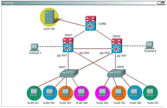
Ferris Plastics, Inc. is a medium sized company, with an enterprise network (access, distribution and core switches) that provides LAN connectivity from user PCs to corporate servers. The distribution switches are configured to use HSRPto provide a high availability solution.
– DSW1 -primary device for VLAN 101 VLAN 102 andVLAN 105
– DSW2 – primary device for VLAN 103 and VLAN 104
– A failure of GigabitEthemet1/0/1 on primary device should cause the primary device to release its status as the primary device, unless GigabitEthernet1/0/1 on backup device has also failed.
Troubleshooting has identified several issues. Currently all interfaces are up. Using the running configurations and show commands, you have been asked to investigate and respond to the following question.
During routine maintenance, GigabitEthernet1/0/1 on DSW1 was shut down. All other interfaces were up.
DSW2 became the active HSRP device for VLAN 101 as desired. However, after GigabitEthemet1/0/1 on DSW1 was reactivated, DSW1 did not become the active router for VLAN 101 as desired. What needs to be done to make the group for VLAN 101 function properly?
A. Enable preempt in the VLAN 101 HSRP group on DSW1.
B. Disable preempt in the VLAN 101 HSRP group on DSW2’s.
C. In the VLAN 101 HSRP group on DSW1, decrease the priority value to avaluethatis less ‘ than the priority value configured in the VLAN 101 HSRP group on DSW2.
D. Decrease the decrement value in the track command for the VLAN 101 HSRP group on U DSWTs to a values less than the value in the track command for the VLAN 101 HSRP group on DSW2.
Correct Answer: A
Explanation:
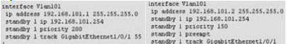
A is correct. All other answers is incorrect. Because Vlan101 on DS1 ( left ) disable preempt. We need enable preempt to after it reactive, it will be active device. If not this command, it never become active device.
Best Cisco 300-115 dumps pdf from google drive: https://drive.google.com/open?id=0B_7qiYkH83VROUdnZWRYLTJta1E
Best Cisco 300-135 dumps pdf from google drive: https://drive.google.com/open?id=0B_7qiYkH83VRS21DRS14UlZHNjg
The best and most updated latest Cisco CCDP 300-115 dumps pdf training resources which are the best for clearing 300-115 exam test, and to get certified by Cisco CCDP https://www.leads4pass.com/300-115.html, download one of the many PDF readers that are available for free. 100% success and guarantee to pass Cisco 300-115 exam test quickly and easily at first try.
New Cisco CCDP 300-115 dumps vce youtube: https://youtu.be/Ud1mstFBjl0